.svg)

PIR Passive infrared
PIR-TFT-550-B
Motion sensor with temperature monitor and ON/OFF delay.
- Need help? Contact us between 8 am – 4 pm every weekday (CET)
- 5-year product warranty
 We arrange shipment to almost every country
- Product information
- Documents
Description PIR-TFT-550-B
Calectro’s motion sensors are primarily intended for use within ventilation and lighting control.
By detecting activity in rooms, it is possible to control the ventilation and lighting only when actually required, thus saving energy.
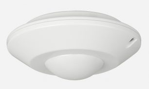
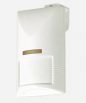
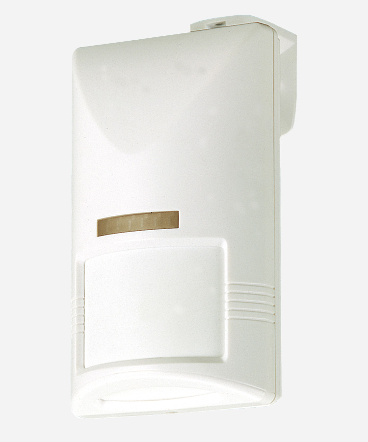
PIR-TFT-550-B motion sensor is a very reliable double-element detector. The sensor is housed in an elegant white cover. The lens has a detection angle of 110° to ensure motion detection in a reliable way. With the supplied mounting bracket MB-99, the sensor can be installed on the ceiling or wall. The ON-and OFF-delays can be selected by means of jumpers.
PIR-TFT-550-B allows the user to set high/low temperature limits. If the room temperature goes above the high-temp limit or below the low-temp limit, the alarm relay will be activated automatically. To disable the temperature limiter: remove the temperature jumper(s).
Installation
Sensor placement:
Locate the sensor so that the probable direction of movement of a person will be across the detection zones. It is easiest for the PIR-TFT detector to distinguish movement in this direction. Avoid possible sources of fault alarms, such as: direct sunlight, strong sources of heat (radiators, copiers, etc.), moving objects such as fans or pet animals, within the sensor’s field of view. Avoid objects that may block the detection area, e.g. large pieces of furniture, curtains, etc.
Installation:
1. Open the front cover by loosing the locking screw. Remove the circuit board from the bottom case.
2. Select wall, corner or ceiling installation. Then punch out suitable “knock outs” for the screws and fit the case bottom.
3. Replace the circuit board and connect the wires.
4. Remember to seal all unused cable entries and screw holes to stop false alarms caused by insects, etc.
5. Replace the front cover; the walk test can then proceed.
6. NB: Before changing the delay settings, switch off the sensor supply voltage.
Walk test:
First ensure that the delay jumper connectors are in the “A” position (shortest delay). Turn on the power supply and wait for about 45 seconds for the sensor to warm up. Now perform the walk test by walking slowly through the entire detection area; pass through all detection zones while keeping an eye on the walk test LED. The LED should light every time you change zones. Let the unit stabilize for about 2 seconds between each test.
Properties
- OFF delay: selectable 5 seconds to 30 minutes
- ON delay: selectable 0 to 10 minutes
- 24 V AC/DC power supply input
- One change-over output
- Temperature monitor